- Aluminium is the most abundant metal on the earth’s surface and the third most abundant element.
- Bauxite is the ore from which aluminium is produced commercially.
- At first aluminium was priceless, but by 1852 price was down to Rs 53,000/- per Kilo, by 1855 to Rs 15,000/- per Kilo and by 1859 down to Rs 1628/- per Kilo.
- Hall’s process immediately lowered the price of aluminium from Rs 968/- per Kilo to Rs 194/- per Kilo & present cost of Al per kilo is around Rs 85/-
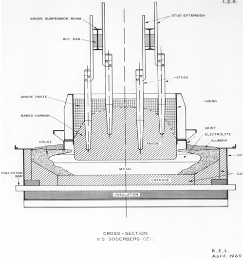
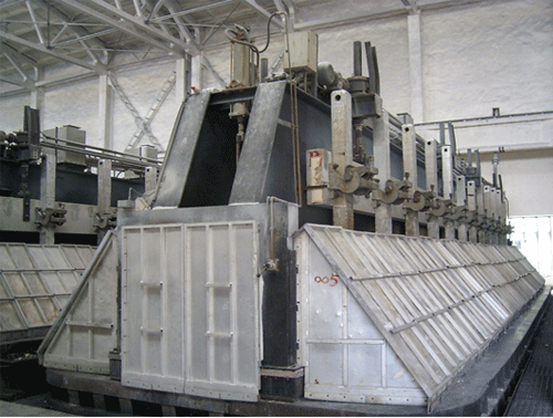
V S Soderberg cell
Although the earliest commercial aluminium reduction cells used prebaked anodes, technology developed to using a self baking “Sodergerg” anode as cells became larger. The single anode was supported on large steel spikes or stubs which were connected to the anode beam.
The spikes were baked into the anode vertically as shown opposite (VS Soderberg cell) or horizontally, as in the HS Sodergerg cells. The consumed anode is replaced with briquettes made from a mixture of calcined petroleum coke and pitch which are regularly added to the top of the anode.
As anode baking technology improved, there was a move back to prebaked anode technology as it was much easier to enclose these cells for fume collection to improve both the internal and external environment.
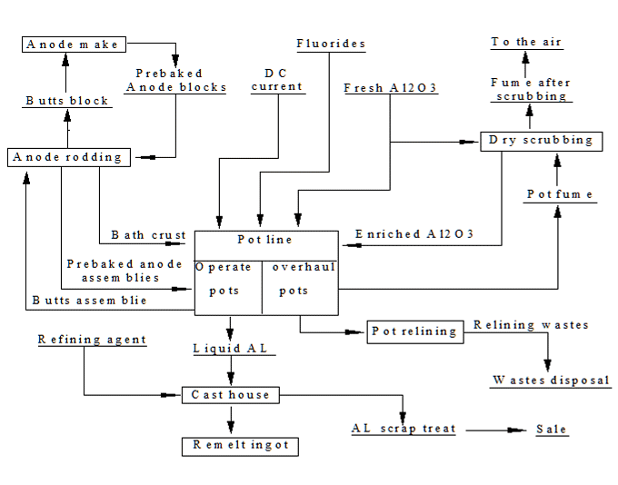
Aluminium Production Process Diagram
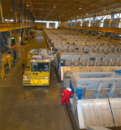
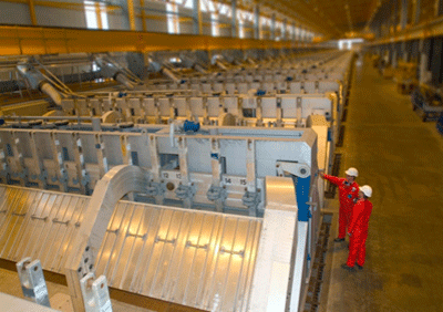
Typical construction of 320 KA pots
The reduction pot is composed of upper structure (anode part) and cathode structure.
Pot upper structure (Pot shell / Pot Superstructure /Anode beam and various mechanism installed on the pot shell.
The pot upper structure mainly includes: anode assemblies, anode bus bar, anode jacking mechanism (raiser), crust breaker/material feeding device.
1. Anode assemblies
Number of anode assemblies for each pot :
40 anode assemblies are arranged in 2 rows along the 2 anode beam with the aluminum rod fixed on the beam by the anode clamps while the joint between the aluminum rod and the steel stub shall be made by explosive welding clad.
2. Anode bus bar
An anode bus bar assembly of each pot consists of 2 sections of aluminum profiles welded with flexible respectively and the 2 bus bars shall be integrated through a balance bus bar.
The contact surface between the anode beam and anode rod shall be machined .
The anode bus bar shall be fitted with box clamps and welded with electrical feeding flexible.
Anode jacking mechanisms (raisers) fixed with 8 hanging points for hoisting the 2 bus bar assemblies.
3.Anode jacking (raiser) mechanism
Each pot shall be designed with 2 set bus bar jacking systems. The bus bar jacking mechanisms (motor+reducer) are respectively installed at both ends of reduction pot with the one at tapping end marked as number “1” mechanism while the one at fume duct end marked as number “2” mechanism.
4.Crust breaking/(material) feeding device
Crust breaking/(material) feeding device includes point feeder, daily (bin) hopper and crust breaking mechanism. Each reduction pot fitted with 5 crust breaking/alumina feeding mechanisms and one fluorides feeding device while specially equipped with a crust breaker for tapping application.
Pot cathode structure:
Including steel shell and pot lining
1.Pot shell
Pot shell is cradle framed, small boat shaped, double strip enclosed and welded by long side plate, short side plate, long side cavity plate, bottom plate and cradle bracket.
2.Lining structure
Bottom (from the bottom to the top):
1 layer of calcium silicate insulating slab 65 mm
2 layers of insulation bricks 2x65 mm
1 layer of dry penetration proof material 175 mm
1 layer of cathode block 450 mm
Sidewall:
The shell side shall be built with 1 layer of 120 mm compound carbon blocks. Underneath the compound carbon blocks at long side are high strength castables and expansion joint brickwork while underneath the same at the pot end shall be the light castables. All the bottom-block seams and the joints with the side blocks shall be rammed with carbon paste. An artificial ledge shall be built with carbon paste in the cavity and the seams between the side blocks shall be bond with binding agent.
Bus bar arrangement :
The bus bar arrangement shall be designed in accordance with hydro magnetic simulation and bus bar section optimization software, and with 5 riser electrical feedings, average magnetic field 4.358 Gs in the cavity and the average velocity of liquid metal 3.65cm/s.
Pot Room Layout :
The pot line shall consist of two pot rooms arranged in parallel each with a length 1043.2 /1115 /1229 m and width 27 m. Each pot room shall be housed with 144 /152 /168 pots in parallel arrangement and divided into 4 sections, i.e. 36 /38 /42 pots in each section while 2 pot rooms shall be housed with 288 pots in total.
Smelting process technology of GP-320 (Ⅱ)
- Current intensity 320 kA
- Alumina concentration 2—3 %
- Thickness of the bath material 20—22 cm
- Thickness of the liquid metal 18—20 cm
- Smelting temperature 945—955 oC
- Molar ratio 2.1—2.3
- Pot working voltage 4.16 V
- Pot average voltage 4.20 V
- Anode effect factor 0.1 times/pot/day
- Time duration for each anode effect 5 min.
Anode Change Operation
Anode consumption is the same for all anodes.
- Anode are changed on a routine schedule to a set pattern.
Whats needed:
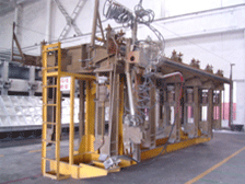
- the crane (“Pot Tending Machine”), a new anode,
- space on a pallet for the butt, a pallet and tools
What do we do: - break the crust in front of the old anode
- remove the butt
- measure its height
- clean the open cavity
- mark the height of the new anode
- place the new anode in the vacant stall on its mark
- clean the area
- later: cover the new anode with cover material
- and check that it has been set correctly.
Anode Bus bar raising
Anode raising/lowering
Anode bus bar raiser and the trip counter shall complete anode raising/lowering procedure. When pot controller gives a command for anode raising/lowering, the pot controller shall first actuate the 2 bus bar raising mechanisms and start raising or lowering the 1# and 2# bus bar raisers simultaneously. At the moment, the strip counter attached to each raiser shall rotate to display the bus bar position and upper/lower limit protection information.
Various plant in side a Smelter plant and their function.
The Smelter plant consist of 3 measure production unit i.e. Pot line, Carbon plant and Cast house.
Pot line :
Normally 2 pot rooms are constructed one pot line. The production capacity of each pot is approx. 2200 kg. per day. The pot room contains Pot Tending Machine (PTM) Anode Transport Vehicles (ATV), Metal Transport Truck (MTT), Suction Laddles and Pouring laddles.
Carbon Area :
It consist of 3 major production unit for production of anode. They are green anode plant (GAP), Baking Furnace (BF) and Rodding shop. The function of each of the above plants are described below.
GAP :
At GAP, green anode are manufactured and the measure raw material required for manufacturing green anodes are Petroleum coke, coal tar pitch and consumed butts.The major machineries involve in GAP are various types of crushers, ball mill, cyclone separators, mixture, coolers, Vibro compacting unit and various types of material handling equipments like overhead conveyor, belt conveyors, screw conveyors and pneumatic conveyors. In brief the coke and butts (consumed anode) are crushed to required size and mixed in the mixture with molten pitch to make a paste. The paste is conveyed to vibrro compacting unit and a green anode is produced in vacuum and further conveyed through a cooling tunnel on a overhead conveyor and finally stacked by a staking crane in the storage as green anodes.
Baking Furnace –
The green anode produced from the GAP are conveyed to baking furnace for baking the anode at a temperature of 11600 centigrade to achieve a baked anode. The green anode are stacked in side the pit of baking furnace where the control heating is done to make a baked anode. The time of baking differs from plant to plant and a baking cycle of 24 to 28 hrs is required in the present production process.
Rodding Shop –
The Rodding shop mainly consist of 3 different units viz. rodding, Butt Crushing System and Bath Crushing System. The rodding shop receives consumed anodes from pot line through ATV in a pallet. The consumed anode mainly consist of stem bracket assembly, bath and the consumed anodes (butt). Initially, the butt passes through a tilting station, where the bath from the pallets are emptied for processing in the bath crushing system. The hard crushed bath adhered to the anode surface are cleaned in the bath cleaning system and the recovered bath is conveyed to bath crushing system for crushing and stored in a silo. The butt is cleaned in the short blasting machine and the cleaned butt is conveyed to butt stripping station for stripping of butt from the consumed rodded anode and the butt is conveyed through various crushers like jaw crushers, roller crushers and screens to get the required size. The crushed butts are stored in the silo for supply to GAP. After the stripping of butts and bath the stem bracket assembly passes through thimble press, where the cast iron thimbles are stripped and the bracket assembly sent to rodding station after inspection of ok brackets. In the rodding station, the anode from the baking furnace is assembled with the ok brackets received from thimble press for making a fully new anode assembly ready for casting. For casting, cast iron furnaces of medium frequency are used for sealing of the anodes with the stem bracket assembly. The final rodded anode are sent to hooking unhooking station for palletizing in the pallets and transported to pot line or storage yard through ATV or 12 T forklift.
Cast house –
The cast house mainly comprises of holding furnace as well as melting furnaces of capacity 35 to 45T. The metal from the pot line are transported through MTT to the furnace. The furnaces are operated either by liquid fuel or by electrical heating system. The molten metal from the furnaces are casted ion the form of ingots, saw moulds, billets, strips and foil etc.
